Warnings on watertightness in the Output Information pane
When creating a structural model using the 'Create watertight surfaces' option on the Construct Surfaces form (model > 3D Structure > Structural Modeling), the Output Information pane (Workspace > Panes > Output Information) might display one or more warning messages which might be valuable to you. These messages are triggered by the watertightness algorithm in case issues were encountered regarding discontinuities (faults, unconformities and intrusions) and due to that, full watertighness could not be achieved.
In some cases, warning messages can be triggered while the constructed surfaces are watertight. When this occurs, the achieved watertighness can be considered coincidental, and it is still strongly recommended to resolve the root cause that triggered the warning message to avoid potential issues in subsequent modeling steps.
Warning message(s) in the Output Information pane
The following message(s) can show up in the Output Information pane:
Watertight structural model:
One or more of the following issues were detected that might impact the watertightness of the constructed surfaces. Most issues stem from discontinuities in relation to the constructed surfaces. It is recommended to manually inspect these issues (refer to the Help for possible solutions):
The above warning appears when a QC grid discontinuity (often a fault), is extended more than the associated tri-mesh input discontinuity of the fault model, resulting in the constructed surface to 'hit' that discontinuity and displaying a gap (see image below).
Suggestions to resolve
Visualize the reported QC grid discontinuity, compare with the tri-mesh input discontinuity, and decide whether the constructed surface should or should not be crosscut by the discontinuity:
- If the constructed surface should be crosscut by the discontinuity, extend the tri-mesh input discontinuity.
- If the constructed surface should not be crosscut by the discontinuity, you have two options:
- Manually connect the parts of the constructed surface with the editing tools (Workspace > Tools > Editing Tools).
- Retract the tri-mesh input discontinuity further so the QC grid discontinuity will no longer crosscut the constructed surface.
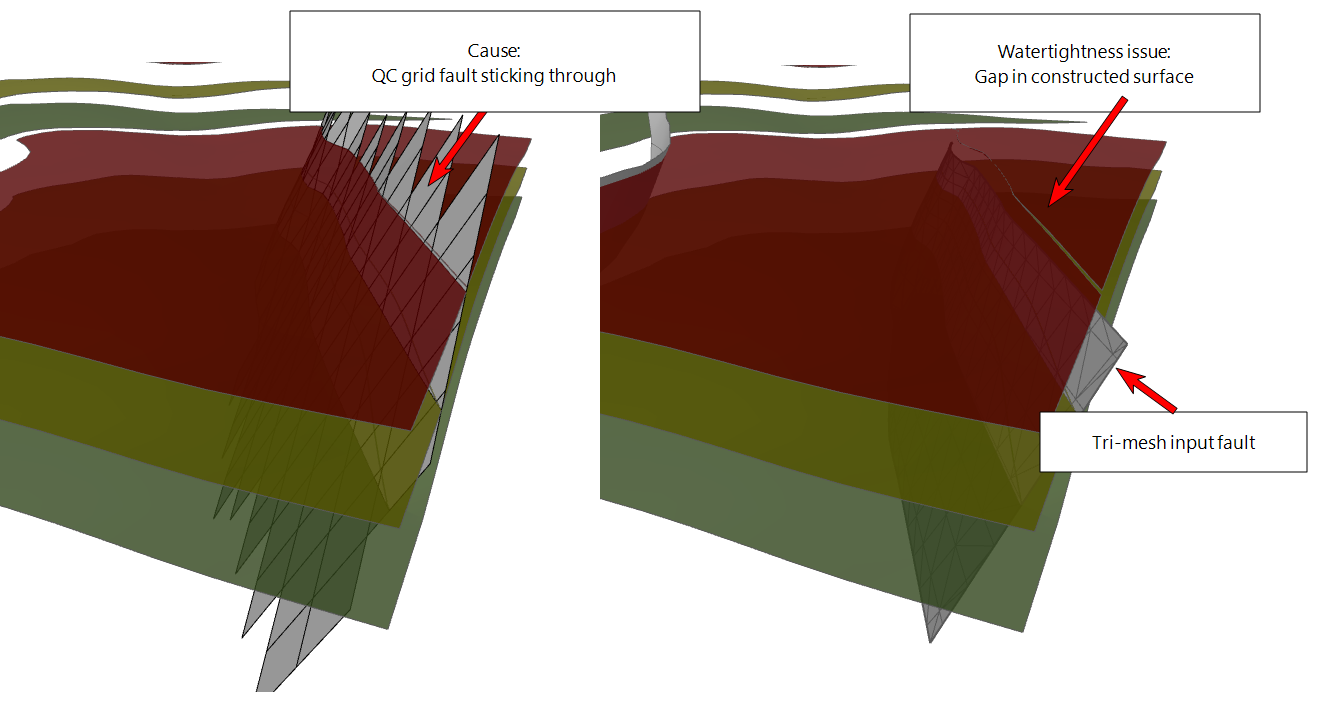
Example of a QC grid fault extending further than the tri-mesh input fault of the fault model, resulting in a gap in the constructed surface. click to enlarge
click to enlarge
Click here to go back to the list of warning messages.
The above warning is typical for situations where discontinuities in the fault model have a (small) gap at their intersection (see image below).
Suggestions to resolve
Revert back to your fault model, and do one or more of the following (do not forget to re-assign the fault model afterwards):
- Make sure the fault intersections are properly resolved in the fault modeling workflow.
- If issues remain, use the 'Diagnostic Tool' in the Tools section of the model > Faults strip in combination with visual inspection to find the gap.
- If gaps remain, or when faults stick through other faults, use the retract/extend tools (under the Structure Builder button on the model > Faults strip).
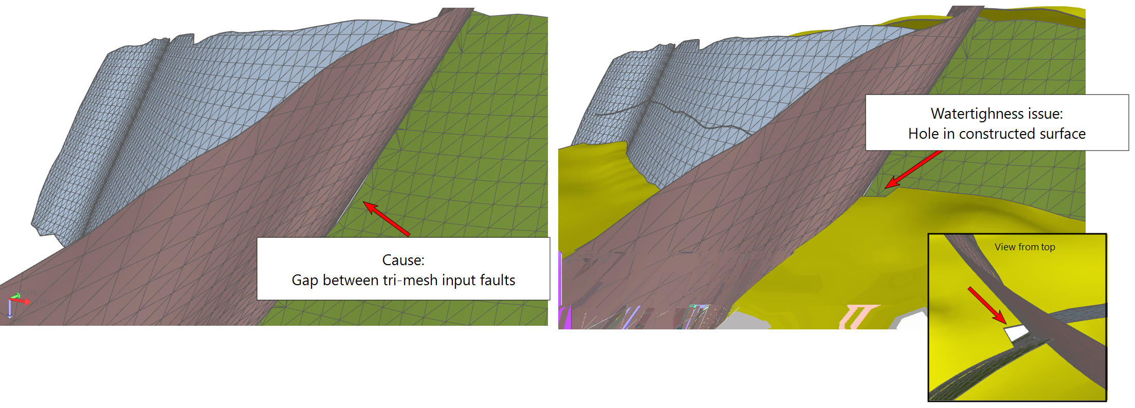
Example of a small gap between two faults, resulting in a hole in the constructed surface. click to enlarge
Click here to go back to the list of warning messages.
Tri-mesh input discontinuities should always extend beyond the edge of your Structural Model to avoid watertightness issues in constructed surfaces at the model's edge. When you receive the above warning, one or more of your tri-mesh discontinuity surfaces have not been extended far enough:
If you use a boundary (or when you have an unconformity assigned to the fault model which is not field-wide), depending on their shapes, there is the possibility that the edge of your Structural Model is not laterally as extensive as the rectangular QC grid Area (see image below and further explanations in Lateral extent of the Structural Model and 3D Grid.) In this situation, the warning can be a ‘false positive’, meaning that although the issue is (technically) identified, it occurs outside of your model’s edge (see next paragraph).
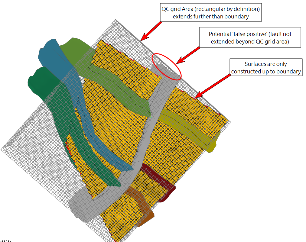
Example of a potential 'false positive', which means a warning message is triggered while the structural model is watertight. This is due to the fact that the issue occurs outside of the model boundary. click to enlarge
False positives (i.e. warning messages that cannot be linked to an actual problem) can occur when a boundary (or an unconformity assigned to the fault model which is not field-wide) results in constructed surfaces which are less extensive than the rectangular QC grid Area. The warning message is triggered by an issue which occurs outside of your Structural Model, but inside the rectangular QC grid Area. This means that within your Structural Model, there is no issue and the surfaces are watertight (see image above). It is nevertheless recommended to solve the issue, see 'Suggestions to resolve' below.
Suggestions to resolve
Whether or not the warning is a false positive, it is recommended to always extend the reported discontinuity up to (and preferably beyond) the edge of the QC grid Area.
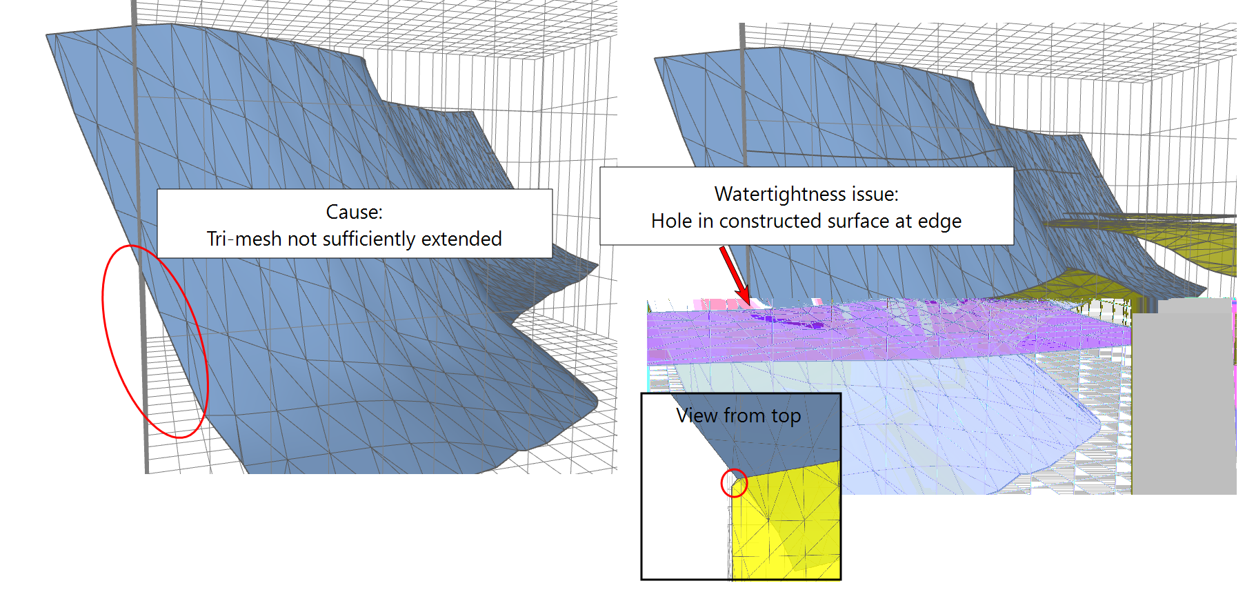
Example of a tri-mesh input discontinuity (the blue fault) which does not extend far enough beyond the QC gri Area. click to enlarge
Click here to go back to the list of warning messages.
The above warning is typically triggered when a fault is not extended enough (up/down or sideways), so that a (to be) constructed surface 'hits' the fault at multiple locations, rather than at one continuous intersection. This would typically occur in situations where such issue is more difficult to spot, e.g. in a model with many faults and constructed surfaces based on markers. Note that the watertightness algorithm always works best when an intersection between one surface and one discontinuity is represented by one continuous intersection, instead of multiple intersections.
The image below demonstrates the principle. The constructed surface (in brown/yellow) has multiple intersections with a discontinuity surface (the blue fault). The constructed surface shows watertightness issues around the intersection. Note that the gaps along the intersection, as clearly shown in the right image, is an extreme case; in many cases, when this warning appears, the respective intersection does not show a gap but will still consist of an undesirable, non-watertight connection (e.g. the horizon pulled down to the edge of the fault).
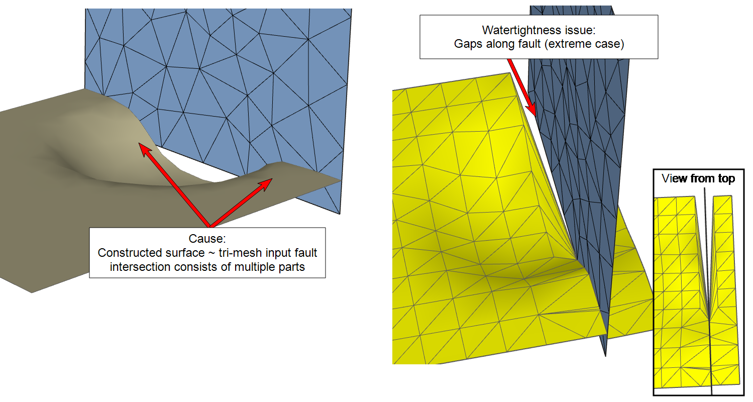
Multiple intersections of the constructed surface (in brown/yellow) with the tri-mesh input discontinuity (blue fault) leads to watertightness issues at the intersection (right image). Note that gaps do not always occur, and the issue can exist of undesirable , non-watertight connections which are more difficult to spot. click to enlarge
Suggestions
Extend the tri-mesh input discontinuity (up/down or sideways, depending on the situation) so that only a single intersection per constructed surface remains (see example below, where the surface was extended downward).
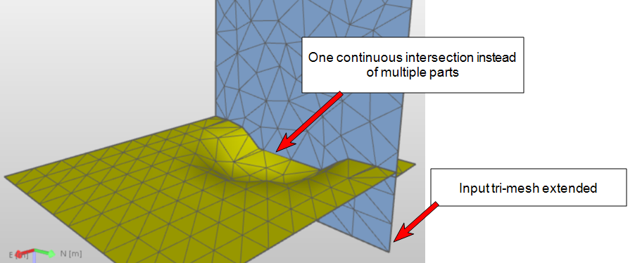
Due to extension of the tri-mesh discontinuity (blue fault), the intersection between the constructed surface and fault consists of one single intersection, resulting in a watertight intersection. click to enlarge
Click here to go back to the list of warning messages.
When an input discontinuity consists of multiple patches and/or has a hole, this can lead to watertightness issues due to the fact that multiple boundaries are detected for the same surface. A common cause is a fault consisting of multiple tri-mesh patches because it is offset by one or more other faults; as a result, multiple boundaries are detected which lead to watertightness issues in the corners of the constructed surface (see image below).
Another cause can be when a discontinuity (e.g. a fault) contains a hole. Also in this case, multiple boundaries are detected, which can lead to watertightness issues.
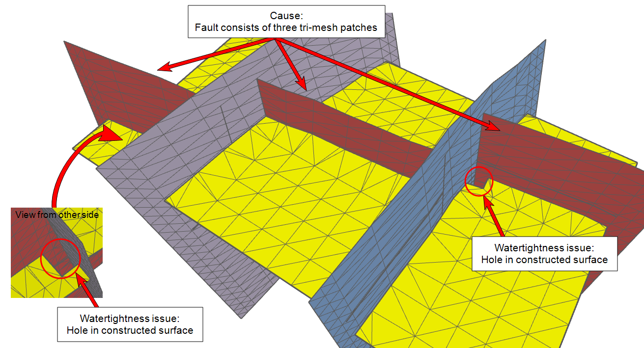
Example where the red fault, which itself is offset by two faults, is set-up as one fault. This causes watertightness issues in the constructed surface at the intersection corners. click to enlarge
Suggestions
The root cause is the detection of multiple boundaries at a single fault. Check for the following:
- Make sure to model faults, which itself are offset by other faults, as separate faults (i.e. not as one fault consisting of multiple tri-mesh patches)
- Remove small/irrelevant tri-mesh patches from faults
- Close any holes in faults
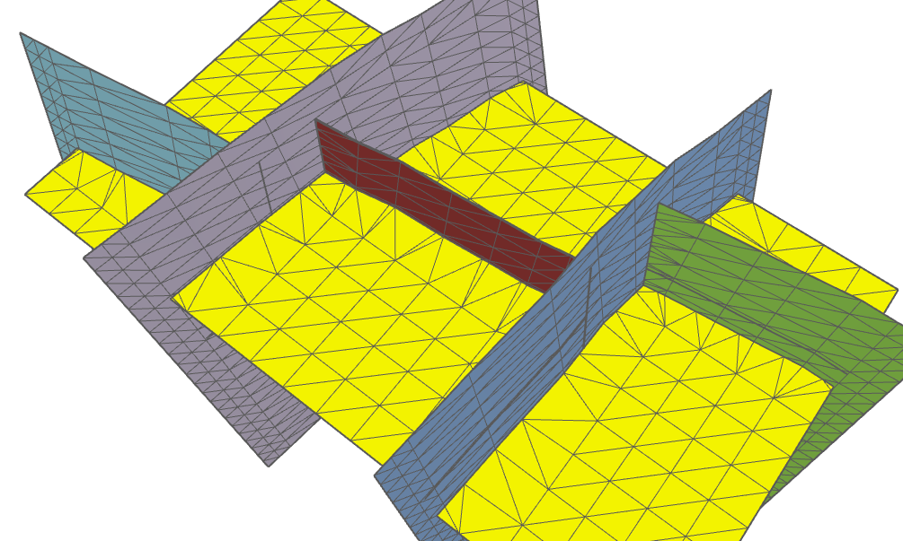
What was previously one fault consisting of three tri-mesh patches (see red fault in previous image) is now modeled as three separate faults (green, red and aqua blue). The constructed surface no longer shows issues at the intersection corners. click to enlarge
Click here to go back to the list of warning messages.